Posts

Capacitor banks and reactors

Image
Capacitor banks and Reactors We have already discussed the significance of reactive power in a power system, As we know the availability of reactive power depends on the excitation of the alternators.This reactive power can be provided by the generators themselves, through the adjustment of generator excitation, but it is often cheaper to provide it through capacitors, hence capacitors are often placed near inductive loads to inject reactive power.the so called capacitors are mainly of two, static condensers and synchronous condensers. The synchronous condensers have a variable value of VAR which can be varied by the excitation of the synchronous motor and the static capacitors have a fixed value of VAR.                                       The capacitor bank simply means that a group of  individual capacitors connected in  parallel and series accordingly to the design of the capacitor bank and together have a value in KVAR or MVAR. Capacitor Connection  A reactor is connected i

DISTANCE PROTECTION

Image
From the name itself it may lighten that it’s about the transmission line protection strategy. Ø   When do we need this?      We need to protect a long transmission line with good sensitivity and selectivity Ø     Why not over current Protection? Of course it is possible as it’s a cheaper. But not recommended where we need higher sensitivity and selectivity. That is, if the load current and fault current are almost comparable, overcurrent protection fails to distinguish between the two. Also it is more susceptible in taking action with the change in fault location. Ø     Advantages over other methods ·          Provides faster operation. ·          Has the directional feature. ·          Greater accuracy as more information is using for taking decision. ·          As a backup protection for cable differential. ·          Independent of source impedance. ·          To detect fault location from the recorded fault impedance. Ø   How its working? The Distance prote

TRANSFORMER COMMISSIONING

Image
Insulation Resistance All know that the resistance of a pure insulation is infinity. But to no extend we can make a pure insulation. So we have a small leakage current to flow through insulation depending upon the voltage applied. Thus as the result we get a resistance value in the range of Mega Ohms(MΩ) or Giga Ohms(GΩ).   Here the applied voltage is DC. We have separate kit for injecting the DC voltage. Usually that equipment is known as megger. The two windings are connected as in the diagram above and Megger is used to measure the insulation resistance. It applies a high voltage normally 500V or 1kV for time period of minimum 30 seconds to One minute and the respective resistance are noted down. Usually for a new transformer, result value will be in Giga Ohms(GΩ). During the ageing, deposition of dust, moisture and other unwanted particles can cause the megger value to reduce. So to gain the resistance back to normal, the dust deposited should be removed, moisture should be

Circuit Breaker Faliure / Local Breaker Backup

Image
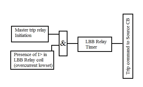
50Z / 50BF / LBB / CBF Ha..! Ha..! Don't get confused upon reading the title. The explanation is just here..! This is another level of protection given for particular circuit breakers. Each power system equipment like transformer, generator, transmission line, etc. have its own protection relay which assures its smooth working and safety. When a fault occurs, one or more protection devices will operate and issue a trip command to the relevant circuit breakers. Operation of the circuit breaker is essential to isolate the fault and prevent, or at least limit, damage to the power system. For transmission and sub-transmission systems, slow fault clearance can also threaten system stability. But most of the time the circuit breaker works fine, but due to some external fault on the circuit breaker such as trip circuit lose contact, delayed circuit breaker operation, circuit breaker’s internal mechanism issue, etc. it fails to trip for the command of different relays . Here c

Differential Protection Scheme (Transformer)

Image
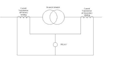
Hey friends! you are familiar with the power system equipment which we discussed earlier.! Now it's time to protect it to total safety. As soldiers protect our country from enemies likewise our system should be protected from fault. The line of control is decided by fixing the current transformers on the right place. So our boundaries is decided by their location. Here in a substation, we have many equipments such as transmission lines, bus-bar, transformers, etc in the system which need atmost care. Starting from the bulkiest, transformers are having different level of protections such as phase to phase and phase to ground. In other words differential protection and earth-fault protection. Over-current protection is also implemented in it. Let's talk about the differential type of protection for transformers. It's quite simple to explain the theory but some complicated while coming into the calculation. The term itself gives a brief idea about the