Differential Protection Scheme (Transformer)
Hey friends! you are familiar with the power system equipment which we discussed earlier.!
Now it's time to protect it to total safety.
As soldiers protect our country from enemies likewise our system should be protected from fault. The line of control is decided by fixing the current transformers on the right place. So our boundaries is decided by their location.
Here in a substation, we have many equipments such as transmission lines, bus-bar, transformers, etc in the system which need atmost care.
Starting from the bulkiest, transformers are having different level of protections such as phase to phase and phase to ground. In other words differential protection and earth-fault protection. Over-current protection is also implemented in it.
Let's talk about the differential type of protection for transformers.
It's quite simple to explain the theory but some complicated while coming into the calculation.
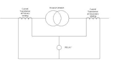
The term itself gives a brief idea about the inspection of safety. Differential means comparison of two quantities at the same time. So here we compare the output of current transformers which is installed at the primary and secondary side of a transformer.
A small diagram which show their connection is given below.
Fig.1 General connection diagram of differential relay.
Fig.2 SLD of internal relay connection
A Differential relay compares the currents on both sides of the transformer. As long
as there is no fault within the protected equipment (Transformer), the current circulates
between the two CTs and no current flows through the differential element. But for internal
faults the sum of the CTs secondary currents will flow through the differential relay making
it to operate.

Fig.3 Actual connection diagram of differential relay.
I1 and I2 are the primary and secondary current respectively. O.C is the operating coil ans R.S is the restraining coil for relay operating.
Two basic requirements that the differential relay connections are to be satisfied are:
- It must not operate for load or external faults.
- It must operate for internal faults.
Fig.4 Relay operating characteristics
Operating characteristics of percentage bias differential relay is shown in the figure.
The current flowing through the operating coil of the relay should be nearly zero during
normal operating conditions and when external short circuit occurs.
The lower setting limit to avoid nuisance tripping due to through fault and tap changing conditions is technically set by adjusting the ratio of restraining to operating coil turns.It is generally in between 0.1 and 0.4.


Impressive
ReplyDeletekeep going