Posts

Differential Protection Scheme (Transformer)
Image
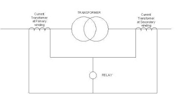
Hey friends! you are familiar with the power system equipment which we discussed earlier.! Now it's time to protect it to total safety. As soldiers protect our country from enemies likewise our system should be protected from fault. The line of control is decided by fixing the current transformers on the right place. So our boundaries is decided by their location. Here in a substation, we have many equipments such as transmission lines, bus-bar, transformers, etc in the system which need atmost care. Starting from the bulkiest, transformers are having different level of protections such as phase to phase and phase to ground. In other words differential protection and earth-fault protection. Over-current protection is also implemented in it. Let's talk about the differential type of protection for transformers. It's quite simple to explain the theory but some complicated while coming into the calculation. The term itself gives a brief idea about the ...

RELAY SETTINGS Part 2

Image
We just gone through the Different Relay characteristics,PSM, TMS and all.Its the time to get hand on these. This could be some what different while coming to practical scenario from the theory part, but hold on you could make it nailed! Typical Overcurrent and E/F relay    Just consider the problem with a fault current of  5000A in feeder equiped with a CT of ratio 400/5A for overcurrent along with a relay setting of  125% .We will see the actual relay operating time with all the relay characterics.   here the rated CT secondary is 5A   then the relay pickup would be 125% of 5A=1.25x5=6.25A   the fault current in the relay coil =5000x5/400 =62.5A   so, the Plug setting multiplier is  62.5/6.25=10   from the Standard Inverse characteristics the tripping time is t=TMS x 0.14/(I r 0.02 -1)  where  I r is the PSM   by taking TMS of 1 tripping time will be  t=1 x 0.14/(10 0.02 -1)     ...

Electrical substation part 2

Image
Electrical substations part 2 Hi there!  In the first part we just gone through a an overview of an electrical substation. Today we are adding a little bit more about the same...    Have you ever wondered how these high voltage high current power system is controlled and protected properly😌. Protection    As we know all the stuffs in the substation are extremely costly, An aquarate and efficient protection system should be established.  And this is achieved by proper relay coordination and various schemes of protection for every equipments such as transformers, busbars,feeders, generators etc... Relays in control panels Control Equipments such as transformers, generators are controlled in a remote control room located few metres away from the equipment yard,here controlling means the switching of relevant circuit breakers of respective equipment. These are achieved by control circuits which are operating at a low voltage dc( eg 110V dc). ...

RELAY SETTINGS

Image
We  chose realys to watch over us, and they does it by any invincible power ? Not at all they are specifically programmed by us for the specific protection  application then how do we do it ? Thats worth something more and we will look into this now . Lets start with the over current protection setting related thoughts. Basically the Relays doesn't prevent the appearance of faults.It can take action only after the fault has been occurred and initiate the opening of switchgear in order to isolate the fault part from the system, so we  must approach into the setting calculation by considering the fault conditions.As the fault discrimination shall have to pick only the faulty part and leave all other part in normal condition, we chose three typical techniques by current, by time and by a combination of current and time. Discrimination by 1.Current It is based on the current at the time of fault and varies according to impedance of the power system elements.B...

Electrical Substations

Image
     Electrical Substations An electrical substation forms an integral part of the power system. It is placed at the both ends of the long distant transmission line... but why??!! Of-course to transform voltage!  A substation at the beginning End or say generation side normally used to boost up the voltage to higher magnitude suitable for transmitting the generated power to long distant load with minimum losses.( Uses a step up transformer )!! Yes the other type is at the other end of the long distant transmission line nearer to load centre... here the high voltage is stepped down to a relevant magnitude which may be used for distribution purpose or another voltage level transmission for near by substations.                    The heart of a substation is nothing but our transformer, depending upon the purpose transformer can be step up or step down!! Now we are considering a load end substation as a...

EARTH WIRE

Image
Ever wondered why there an extra line on top of every transmission line we see.? Ever thought why we use any insulators for that line.? One among the level of protection for the power system is this Earth / Shield wire. As for the power system(OH Line), biggest enemy is the lightning surge. Even though we install arrestors, it solely cannot complete the work. For increased rate of protection we use earth wire on top of the transmission line. The overhead earth wire or ground wire is the form of lightning protection using a conductor or conductors. It is attached from support to support above the   transmission line   and well grounded at regular interval. The earth wire intercepts the direct lightning strikes, which would strike the phase conductors. The ground wire has no effect on switching surges. When the lightning strikes an earth wire at mid-span, waves are produced which travel in opposite directions along the line. The waves reach the adjoining tow...

Vibration Dampers

Image
   How do we control mechanical vibrations generally, yeah by some sort of vibration absorbing techniques.Then, what about the vibrations present on transmission lines ? Well that's indeed a  question. It isn't the rocket science, just a matter of transferring and or dissipating the energy behind it. Lets see how it is engineered.    As the wind passes some of its energy gets transferred to the overhead transmission lines and tends to oscillation(mostly).But as the weight of the conductor is high to limit the oscillation the energy try to get converted to the form of vibration.Vibrations then spread across the conductor length and its not a good thing in mechanical aspects as its causes the deterioration of strength of conductors.In engineering view of thinking it is only avoided by absorbing the energy causing it.The simple way for it is damping those vibrations mechanically from the line itself, that particular concept resulted in the designing of vibrati...

Lightning Arrester

Image
  Lightning.....! the wicked thing in our power system.                     For us it creates only damages. So is important to protect the crores worth devices which support the generation, transmission and distribution of power. Starting from the generating stations, all the power cables are connected to a device which is called surge diverter or lightning arrester. In transmission towers we draw a separate line for earth at the top of the tower. By that line we create a zero potential at the top of tower. Thus protecting transmission lines from lightning surges. Electrical surge produces a large transient over voltage in the electrical network and system. The shape of the transient over voltage has a steeply rising front with slowly decaying tail. There are two types of surges one comes externally from atmosphere such as atmospheric lightning. Second type is originated from electrical system itself, such as swi...

ISOLATORS

Image
What do we do if a circuit breaker or any other power flow controlling device gets faulty and we want to gain control over a device(say a bus or line or transformer,etc) ,Yes there have to be some sort of back up for it ,a master manual switch, which could be used for isolation of one network part from another, called Isolator. It enhances the safety of the maintaining part in the power system by complete de-energizing it. Well ,lets lean on it. Just visualize a switch having capability of circuit disruption, handling of load current, mechanical properties needed for its operation and more importantly as we are dealing with high voltage there has to be a provision for its separation from metal parts in which it is fixed about, for this usually the solution is solid porcelain core type insulators,having high mechanical strength and dielectric strength. Operation                              The...

Current Transformers

Image
  Did we want to really concerned about the current transformers ? Its just an instrument transformer Yeah!,  that's make it different in protective relaying Lets dig deep                             In the most protective relays the input quantity is current and these current are supplied by current transformers. located on or near to the protected equipment. The main functions of CT are 1. To isolate the power system circuit from protection circuit 2.Reduction of magnitude to a level accessed by relays and meters  When considering Constructional features, these are similar to normal transformers consisting a magnetically coupled primary and secondary windings, wound on a common iron core and the primary is connected in series with  the network and the ratio could be found from basics ie,   Ampere-turns in primary=Ampere-turns in secondary ie, low no. of t...